Making of NX11
Agenda
1. Overview
2. Components
3. About M5StickC
4. About DRV8830
5. 3D printing parts
6. PID Control
7. Blynk
8. Sketch
9. Motion check
1. Overview
It seems that the inverted pendulum made with M5StickC is popular, so I made it myself.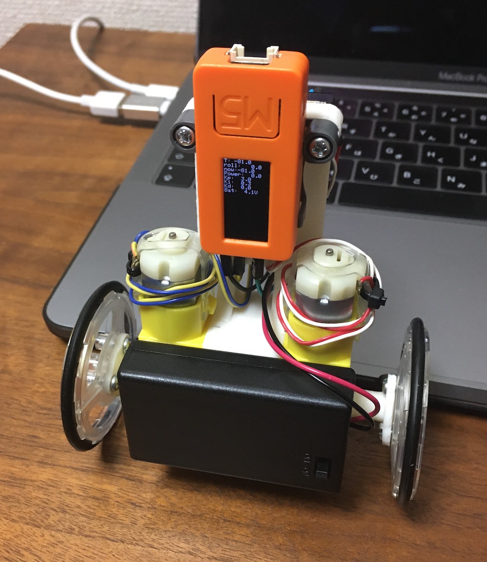
2. Components
1.M5StickC
2)DRV8830 x2 (Akitsuki I2C connection motor driver board
3)DAGU DG01D MINI DC GearBox x2
4)TAMIYA slim tire 55mm x2
5)Mini breadboard
6)Battery AAAx3 and battery box with switch
3. About M5StickC
I wrote about M5StickC on my blog, so please see here.
4.About DRV8830
DRV8830 is a I2C connection motor driver I used Akizuki's board this time.
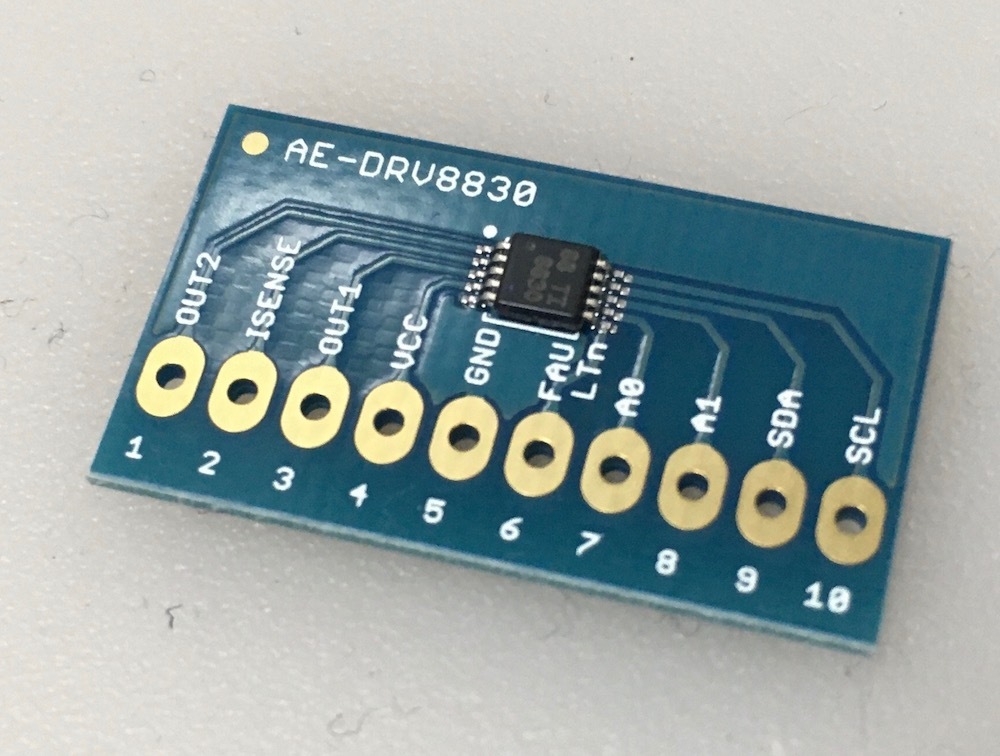
Connections are as follows.
SDA and SCL of I2C were pulled up to 4.5V of the power supply with 2.2kΩ.
Set the I2C address with A0 and A1. This time, it is as follows.
For rightside:A0,A1 Low(GND)→ 0x60
For leftside:A0,A1 Open→ 0x64
The current limit of the DRV8830 is set by resistors R1 and R2.
R=200mV/Ilimit
Since the rated current of DRV8830 is 1A, it was set to 0.2Ω.
The battery must always be above the constant voltage error threshold of 2.75V.
If it is about 3V, it may fall below 2.75V under load and become FAULT.
This time, the alkaline battery is 1.5Vx3 = 4.5V.
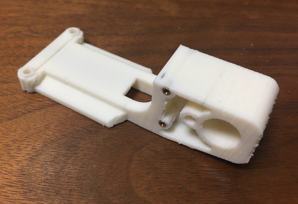
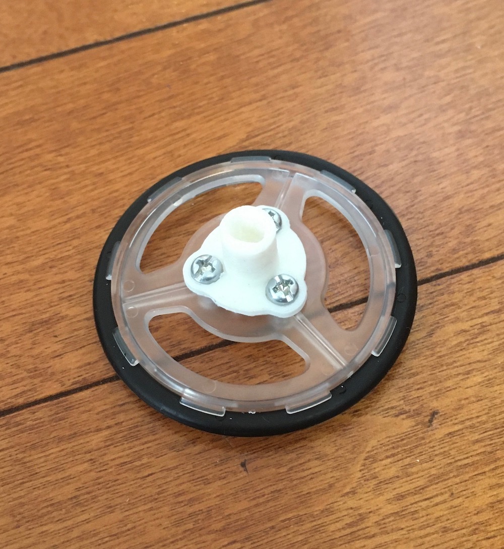
5.3D printing parts
The parts connecting the two gearboxes and the M5StickC were designed with Fusion360 and 3D printed.
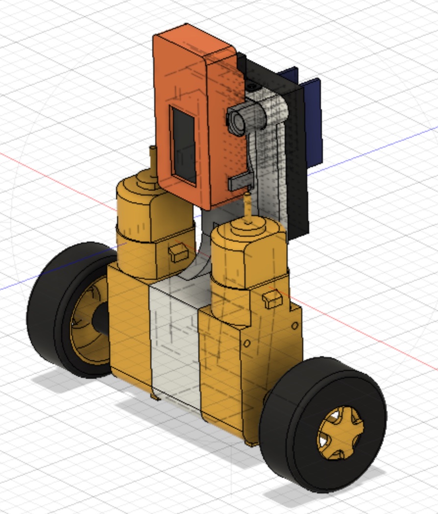
The wheels used were 55mm slim tire sets from Tamiya, but the flanges were 3D printed because they did not fit with the DAGU gearbox.

Also, this time, as a result of trial and error, the weight is added to lower the center of gravity.
Normally, placing the center of gravity at a high position should be stable, but the motor driven by DRV8830 can not catch up
I lowered the center of gravity because I realized that it couldn't place it too high.

6.PID Control
The following sites are helpful for PID control.
The most easy-to-understand explanation of PID control in the universe
7.Blynk
The PID gain can be adjusted using Blynk so that it can be changed slightly from the iPhone.
I wrote about Blynk on my blog, so please refer to it.
8.Sketch
Basically, it was created with reference to the sketches of the following site.
Inverted pendulum PID control with M5StickC-Road to inverted pendulum 3-
Control with inverted pendulum Blynk on M5StickC-Road to inverted pendulum 4-
Super-easy M5StickC inverted pendulum with all 60Steps
See the blog for a detailed sketch.
9.Motion check
The PID gain has been adjusted to be quite stable.
It can stand alone for more than 5 minutes.
I think that the PID gain changes in each environment, but I set it as follows.

Update
- 2020.4.4Created a page for making an inverted pendulum made with M5StickC.NEW