Making of NX10
Procedure
1. Overview
2. Concept
3. System design
About M5Stack
About servo
Servo board
Battery
4. Structural design
About 3D CAD
3D printing
5. Assembly
6. Mac side control application
7. Motion
1. Overview
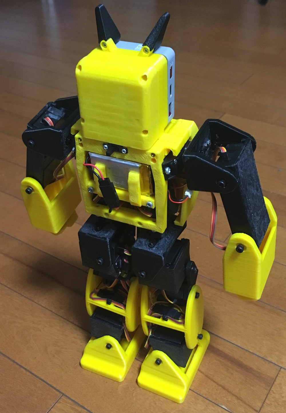
This time I would like to make a biped robot using M5Stack and 18 servos (motors).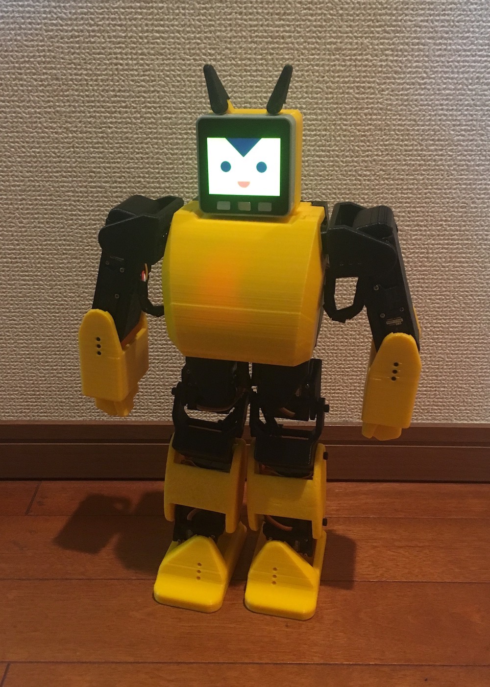

Main components
・Micro2BB 18 servos
・M5Stack Gray
・Servo board
・Ni-MH Battery 6V
・3.7VBattery module
・3D printed servo bracket
Some components may not be understood now, but I will explain them step by step.
2. Concept
First, what kind of robot will you make? You can't suddenly make a circuit using a soldering iron or make a 3D print, so let's first draw a picture on paper while looking at robots made by others on the web. It doesn't matter. This is called a punch picture. It may actually be the most enjoyable time while imagining the finished robot. There are many robots that did not make a lot of punch pictures. It's almost like this.
3. System design
The system components are as follows.
・M5Stack
・18 servos
・Ni-MH Battery 6V for servo
・Lithium ion battery 3.7V Control power supply (spare)

About M5Stack
M5Stack is a module equipped with EPS32, with built-in WiFi and Bluetooth, a liquid crystal display, and a model called Gray with a 9-axis acceleration + gyro + magnetic sensor.
Moreover, Arduino IDE can be used for software development, and it is relatively easy to migrate from Arduino.


About servo
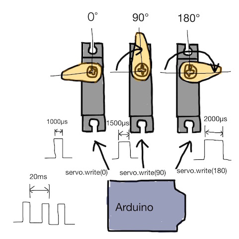
A general DC motor operates to keep rotating at a certain rotation speed when a certain voltage is applied. The servo motor operates to maintain a certain angle with respect to the angle command from the microcomputer. Therefore, it can be said to be a suitable motor for a robot that moves to hold a joint at a certain angle. The angle command is from 0 to 180deg from Arduino. The servo rotates to that angle and keeps the angle at that position.
Microcontrollers such as Arduino and M5Stack specify the servo angle of 0 to 180deg. Actually, a pulse voltage with a time width corresponding to the angle is sent to the servo.
Servo GWS Micro2BBMG used this time
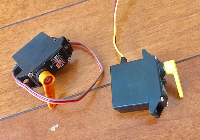 Torque 5.4kg-cm@4.8V
6.4kg-cm@6.0V
Speed 0.17sec/60°@4.8V
0.14sec/60°@6.0V
Weight 26.6g
Dimmension 27.9mmx14.0mmx29.7mm
Servo board
A servo board was created to connect M5Stack and the servo.

In order to move 18 servos simultaneously, 16 are driven by an I2C-connected servo driver called PCA9685 and the remaining 2 are driven directly by M5Stack.
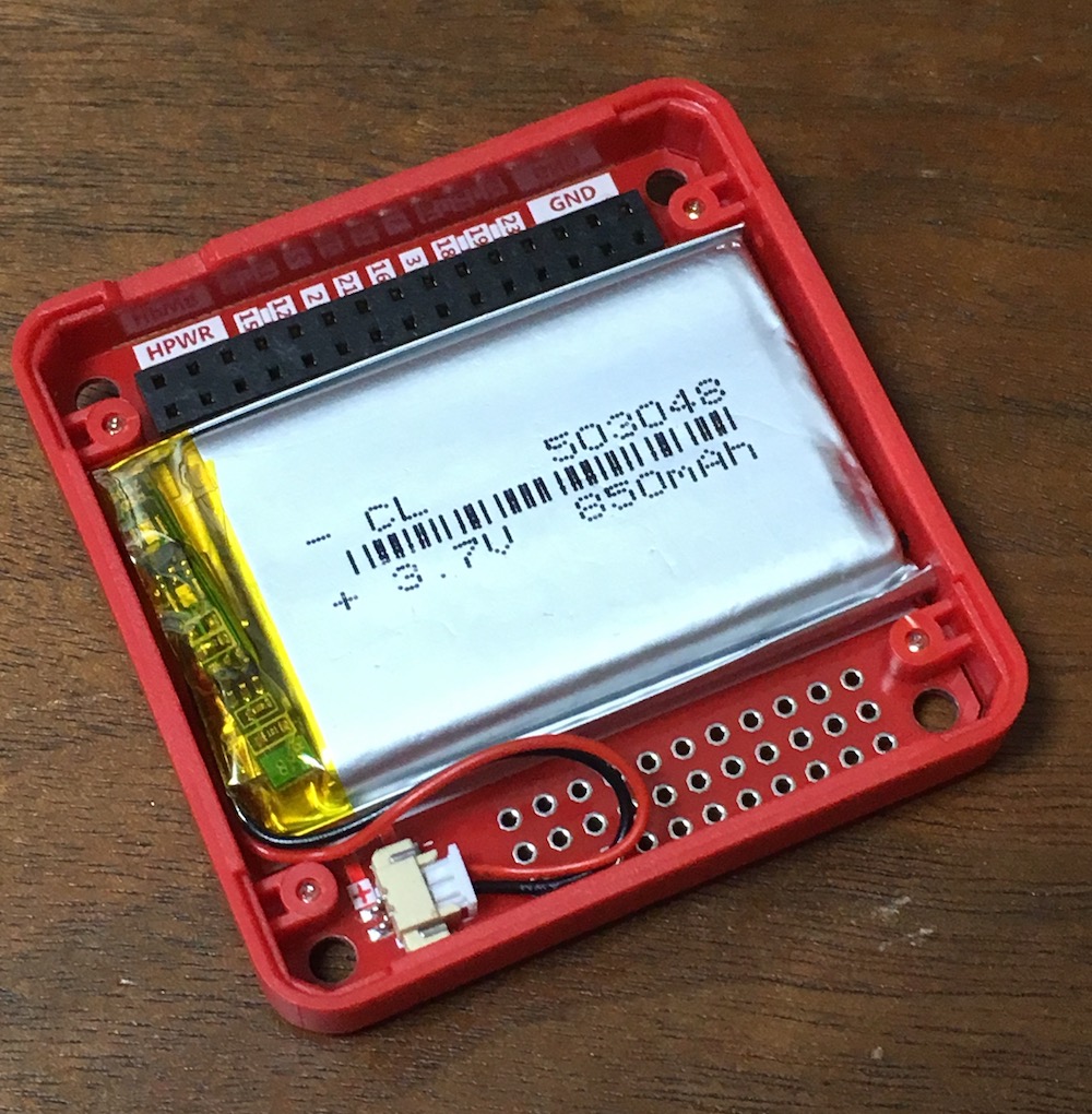
Battery
M5Stack operates at 5V. This time, the control power supply is stepped down from the servo power supply using a regulator, but if a load is applied to the servo, the voltage drops and it may not operate correctly, so connect lithium ion batteries in parallel.

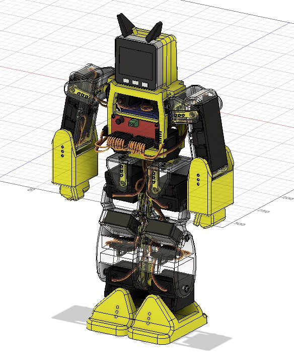
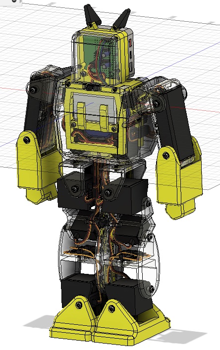
4. Structural design
The frame structure that fixes the servo, builds the robot framework, and attaches the control board uses a bent aluminum plate or 3D printed parts. I used an aluminum plate before, but it is quite difficult to use this, so this time I will make a 3D printed structure. I would like to explain how to make a structure with aluminum plates at another time.
And I want to design 3D printed parts using 3D CAD. This time, 3DCAD used a software called Fusion360.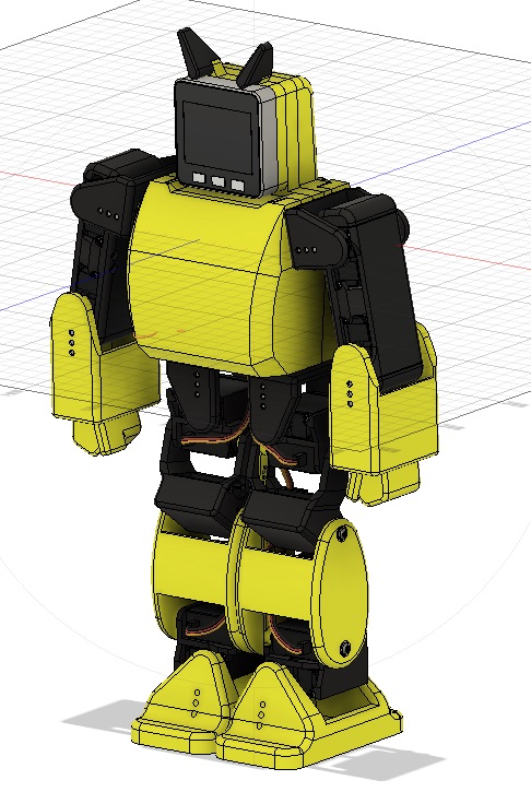
5. Assembly
It is like this after assembly.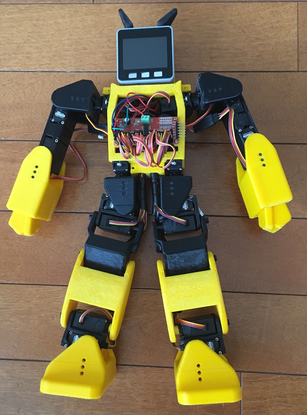
6. Mac side control application
The robot is controlled from the Mac. Connect with Bluetooth. The control app is self-made using Xcode.
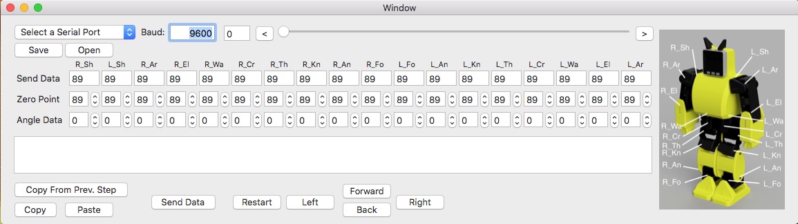
7. Motion
It can be moved backward, turn left and right, slide left and right.
Update
- 2019.8.18Create a biped robot page created with M5StackNEW